Nicholas Day > High Performance Brushless Steppers
2026-07-15
After seeing Ben Katz's blog post on the MIT Mini Cheetah, I've wanted to make high performance actuators like the ones that he did. With the field oriented motor controllers (FOC) that he designed, he's able to run position, velocity, and torque control at >10khz on the microcontroller and ~1-5khz communication for setting targets and reading back values.
There exist many alternatives, but it's a rite of passage for a roboticist to attempt to make these types of actuators.
I chose to start with 2 phase stepper motors because they're very cheap, and high torque relative to their cost yet can still be controled with FOC just like 3 phase motors. They're not very lightweight, but that's fine for stationary applications.
This is what my control loop looks like:
target_d = 1.0 # amps
target_q = 0.0 # amps
phi = sense_mechanical_angle() # void -> radians
theta = map_mechanical_angle_to_electrical(phi) # radians -> radians
a_current, b_current = sense_current() # void -> amps
d, q = phase_to_dq(a_current, b_current, theta) # amps, radians -> amps
d_out, q_out = current_control(target_d, target_q, d, q) # amps -> volts
a, b = dq_to_phase(d_out, q_out, theta) # volts, radians -> volts
set_pwm(a, b)
And here's approximately what my KiCad diagram looks like:
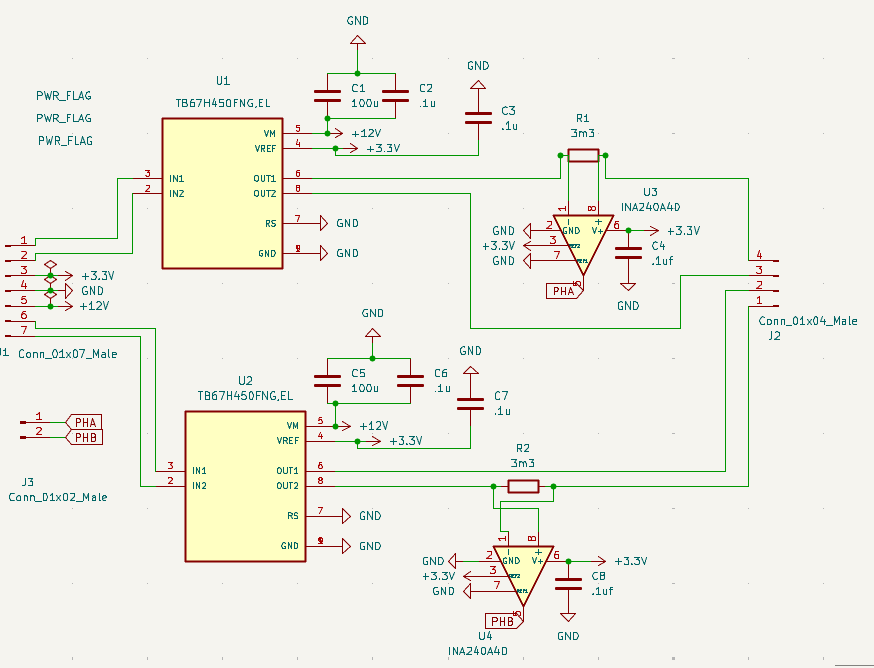
There are 2 full h-bridges, one for each phase, along an inline bidirectional current sensor so that it's possible to determine the correct current and direction at any moment. There is a also separate board with an AS5047p which mounts to the back of a stepper motor with a diametric magnet glued on the end of the shaft.
These circuits are hooked up on a breadboard with a rp2350 microcontroller.
I've since modified this circuit with ~60uF of MLCC bulk capacitance for the DC bus for each individual phase driver.
Electrical Angle Calibration
The unforunate part about stepper motors is that they have 50 electrical pole pairs. So each electrical phase is 7.2 mechanical degrees (360 / 50). That's not very long of an electrical period so the motor control loop has to be fast enough to keep up depending on what velocity is desired. It also means that a lack of resolution or accuracy in the sensed position of your rotor can be very punishing.
I chose to use the tried and true AS5047p sensor because it seemed like others had success with it, and it had 14 bits of resolution. This corresponds to about 327 counts (2^14 / 50) per electrical phase. More would be useful, but higher accuracy sensors generally cost more or offer different tradeoffs. However, even the AS5047p has ~1-2 bits of noise and gives a significant amount of INL (integral nonlinearity) when the alignment is off by as little as .3 mm.
To calibrate the mapping between rotor angle and electrical angle, generally the motor is first locked to 0 electrical angle, then spun at a slow constant velocity by putting a few amps on the d axis and rotating the angle in software. This is how steppers are usually controled. At each open loop electrical angle increment, the angle sensor's value is compared with the electrical angle to give an error that is stored in a look up table. The electrical zero is found by taking the average position. This is done in both forwards and backwards directions to give a more accurate measurement. During the FOC loop, the rotor angle is converted to an accurate rotor angle. Then the electrical zero is subtracted to give an electrical angle measurement.
I tried this, and it didn't work great for me. It still resulted in a lot of unsmooth torque. Either I have a bug in my code, or steppers benefit from a more accurate fit. So I used the stepper steps directly. My new calibration routine was force the rotor to align to electrical zero, wait. Step a full stepper step (1.8 mech degrees) using the inbuilt mechanical accuracy of the stepper. Then wait to let the rotor settle, and take 10 measurements to form an average. This is then sent to the computer. This was the resulting position error vs steps:
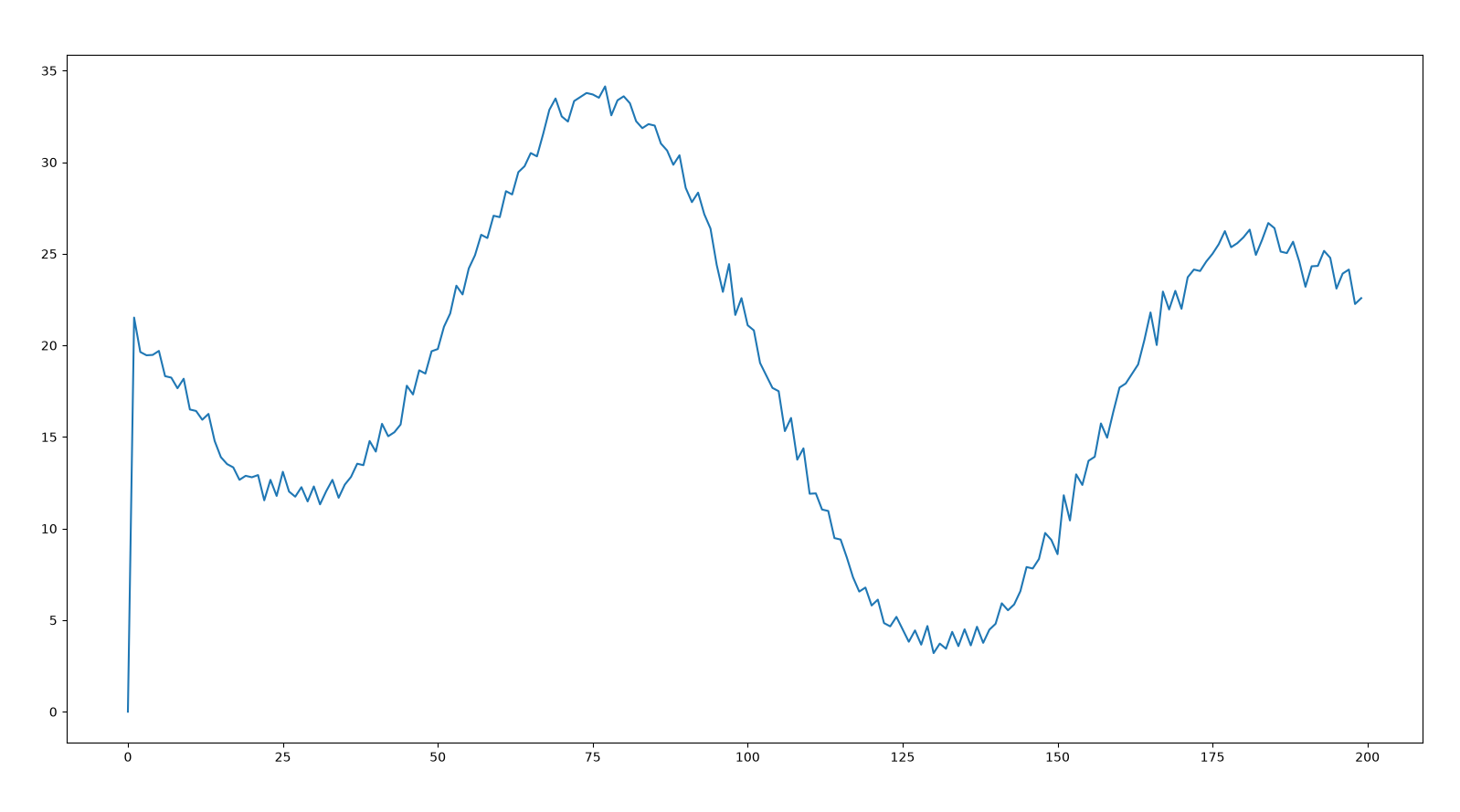
I then made a massive interpolated look up table of 2^14 angle sensor counts -> electrical angle from these sampled points (0, pi/4, 2pi/4, 3pi/4). This replaces the electrical zero parameter from earlier by directly mapping to elecrical angles.
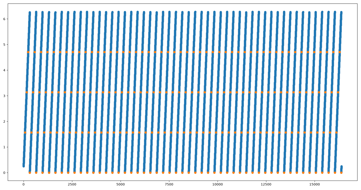
With this, thankfully the stepper moves much more smoothly.
Controlling Current
My intuition for tuning PID loops manually fell short, using a strong P resulted in high oscillations. I then learned it's possible to calculate your Kp and Ki gains directly with some control theory (mjbots). This unsurprisingly gave much better performance.
Two other issues occurred with regards to PWM. It's important to have the have current circulate through the fets when the PWM is in an off state. Otherwise the current decays too quickly which resulting in unpredictable vibration (drv8251a datasheet).
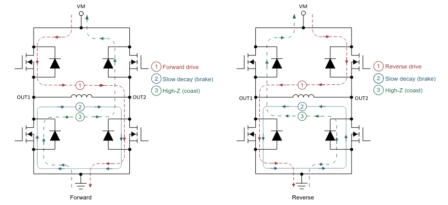
The code to do it is like this:
if voltage > 0:
    pwm_a1(MAX_PWM_COUNTS)
    pwm_a2(MAX_PWM_COUNTS - voltage)
else:
    pwm_a1(MAX_PWM_COUNTS - voltage)
    pwm_a2(MAX_PWM_COUNTS)
This could also be replaced by inverting the PWM polarity.
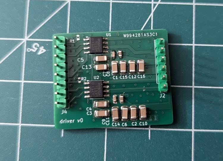
Even with this, I was still experiencing some lack of smoothness, so I designed another board with higher bulk capacitance based on this paper (Selecting Film Bus Link Capacitors For High Performance Inverter Applications). It also features better grounding.
Logging
Occasionally the motor would stutter after a period of time, which pointed towards something that wasn't in the control loop directly.
Printing out debug values takes a long time! And the current control loop shouldn't be interrupted by prints. The solution I came up with was to have the loop run in the PWM wrap function so it interrupts any prints and executes precisely at the point when the next PWM level should be set.
To help with logging the relatively large amount of data (~6 floats at 30khz = 720kbps), I wrote a simple circular buffer to hold the logs and transmit what it can. There are other methods to get higher performance out of your microcontroller with ITM and SWDIO type of fixes. Maybe even the HTX line / PIO on the Raspberry Pi microcontrollers.
What's next?
The current sense samples on the rp2350 take 2uS per read. And there is only one adc which reads sequentially too. This adds lag and noise to the system. I'm eyeing the stm32g431 which has 2 fast and simulataneous ADCs along with other motor control peripherals.
Ideally, analog values would be properly grounded with ground planes and via stitching and maybe a better voltage reference. This should result in cleaner torque control with less noise and vibration in the motor.